Dimensions / Weight
| W | H | D | |
|---|---|---|---|
| Dimensions | 320 mm (12.6 inch) | 132 mm (5.2 inch) | 350 mm (13.78 inch) |
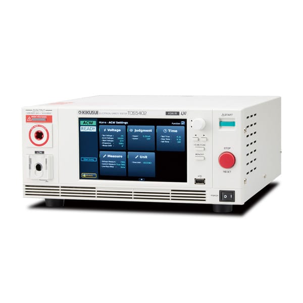
AC Hipot Tester with Insulation Resistance Test
TOS5402
400,000円 (税込:440,000円)
- PWM amplifier provides highly stable output
- AC withstanding voltage test: 5 kV / 100 mA (500 VA) (TOS5401/TOS5402)
- Touch panel display
- LAN, USB, and RS-232C as standard
- Faster output control and measurements support high-speed takt times
Product Overview
New standard models available!
TOS5400 series electrical safety testers are designed to perform two of the four safety tests required for electrical products:
withstanding voltage and insulation resistance tests. With an output of 5 kV / 100 mA (AC) and 6 kV / 10 mA (DC), these devices can perform withstanding voltage and insulation resistance testing of electronic equipment and components in accordance with safety standards such as IEC, EN, BS, VDE, UL, CSA, GB, and JIS, as well as the requirements of the Japanese Electrical Appliance and Material Safety Act. TOS5400 series is also equipped with a highefficiency PWM switching amplifier that maintains stable output voltage even if there are AC line voltage or frequency fluctuations, enabling reliable evaluation even in regions with unstable power supply.
This series is the first of Kikusui withstanding voltage and insulation resistance testers with a touchscreen display, enabling intuitive and efficient operation. Thanks to discharge detection feature the response speed (sensitivity) can be adjusted, allowing detection of momentary discharges and discharges containing high frequency components, including arc and corona discharges. This series also has “Start Long” function (hold the START button to begin a test) which helps prevent accidental test starts.
TOS5400 series is an excelllent choice for a broad range of applications, including R&D and QA testing, cer tification body test facilities and production line inspections.
Simple operation
ensures reliable and safe testing!
Intuitive Operation
Equipped with a 7-inch touch panel.
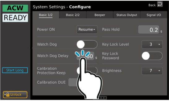
Touchscreen enables intuitive operation. The display shows not only test settings but also overviews and diagrams, making the interface easier to use.
High Stability
Equipped with a high-efficiency PWM switching amplifier!
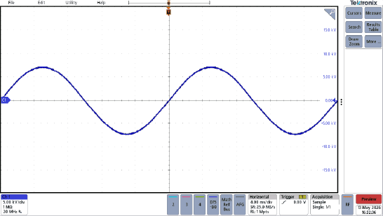
Outputs a stable high voltage unaffected by AC line fluctuations. Allows reliable testing even in regions with large voltage variations. (Input voltage fluctuation rate: ±0.3%)
Shorter Takt Time
Improved productivity!
The start phase shift function* allows tests to be performed without rise time, which, compared with conventional models, shortens takt time and improves productivity.
*Can be set when the Time Unit is set to “cycle”.
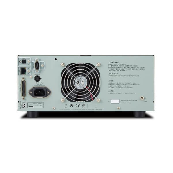
Multiple Interface Options
Compatible with various types of automation!
Equipped with an LXI compliant LAN, USB 2.0, USB compliant with USB-TMC, and an RS 232C interface.
Even momentary discharges can be detected
Current detection sensitivity can be adjusted with the discharge detection function!
The discharge detection function allows adjustment of the current detection response speed (sensitivity), enabling detection of instantaneous discharges and discharges with high-frequency components (supports arc and corona discharges).
Specifications
Withstanding Voltage Test
Output function
AC output section (ACW only)
| Item | TOS5401 | TOS5402 | ||
|---|---|---|---|---|
| Output range | 0.05kV to 5.00kV | |||
| Output setting accuracy | ±(2% of setting + 20V) (at no load) | |||
| Output setting range | 0.000kV to 5.500kV | |||
| 0.000kV to 1.500kV (When Time Unit is set to Cycle and Phase Shift is set to 0°) | ||||
| Output resolution | 1V | |||
| Max. rated output *1 | 500VA (5kV/100mA) | |||
| Max. rated voltage | 5kV | |||
| Max. rated current | 100mA (when the output voltage is 0.5kV or higher) | |||
| Transformer rating | 500VA | |||
| Output voltage waveform*2 | Waveforms | Sine | ||
| Phase shift | The output voltage waveform can start with a phase shifted approx. 90° from the zero-crossing point. | |||
| Distortion | 3% or less. (when the output voltage is 0.5kV or higher and no load or a pure resistive load is connected) | |||
| Frequency | 50Hz/60Hz | |||
| Frequency setting accuracy | ±0.5% (excluding during voltage rise time) | |||
| Voltage regulation | ±10% or less (when changing from maximum rated load to no load) | |||
| Input voltage variation | ±0.3%(5kV at no load; power supply voltage: 90V to 250V) | |||
| Short-circuit current | 200 mA or more (output voltage 1.0 kV or higher) | |||
| Output method | PWM switching | |||
*1 When tests are performed consecutively, output time limit and rest time may become necessary depending on the upper limit setting.
*2Waveform distortions may occur if an EUT whose capacitance is dependent on voltage (for example, an EUT that consists of ceramic capacitors) is connected as the load. However, if the test voltage is 1.5kV, the effect of a capacitance of 1000pF or less can be ignored. Because the high-voltage power supply of the TOS54 series uses the PWM switching method, if the test voltage is 500V or less, the switching and spike noise proportions are large. The lower the test voltage, the greater the waveform is distorted.
DC output section (DCW only)
| Item | TOS5401 | TOS5403 | ||
|---|---|---|---|---|
| Output range | 0.05kV to 6.00kV | |||
| Output setting accuracy | ±(2% of setting + 20V) (at no load) | |||
| Output setting range | 0.000kV to 6.200kV | |||
| Output resolution | 1V | |||
| Max. rated output *1 | 50W (5kV/10mA) | |||
| Max. rated voltage | 6kV | |||
| Max. rated current | 10mA | |||
| Ripple (TYP) | 5kV no load | 50Vp-p | ||
| Max. rated load | 100Vp-p | |||
| Voltage regulation | 3% or less (when changing from maximum rated load to no load) | |||
| Short-circuit current (TYP) | 40mA (when generating 6 kV output) | |||
| Discharge function | Forced discharge after test completion (discharge resistance: 125kΩ)*2 Maximum capacitance: 1μF*3 Discharge time: 0.0 to 100.0 seconds Discharge function during interlock activation: ON/OFF | |||
*1 When tests are performed consecutively, output time limit and rest time may become necessary depending on the upper limit setting.
*2 In the following conditions, charging current may activate a FAIL judgment or trigger the protection function. EUT capacitance: 1μF; Rise Time: 1.0 second or less; Judge Delay: 1.2 seconds or less.
*3 Maximum capacitance that can be discharged within 2 seconds in a DC withstanding voltage test. Tests can still be conducted beyond the maximum capacitance, but the discharge time will increase.
Common specifications
| Item | TOS5401 | TOS5402 | TOS5403 | ||
|---|---|---|---|---|---|
| Start voltage function | The initial voltage at test start can be set to 1% to 99% of the test voltage. Resolution: 1% | ||||
| Disabled if the Time Unit is set to Cycle. | n/a | ||||
| Limit voltage function | The upper limit of the test voltage can be set. ACW: 0.000kV to 5.500kV, DCW: 0.000kV to 6.200kV | ||||
| ACW: 0.000kV to 1.500kV (When Time Unit is set to Cycle and Phase Shift is set to 0°) | – | ||||
| Output voltage monitor function | If the output voltage deviates more than ±(350V) form the set value, the output is turned off, and the protection function is activated. | ||||
Measurement function
Digital voltmeter
| Item | TOS5401 | TOS5402 | TOS5403 | ||
|---|---|---|---|---|---|
| Measurement range | AC/DC: 0.000kV to 6.500kV | AC: 0.000kV to 6.500kV | DC: 0.000kV to 6.500kV | ||
| Display | □. □□□ kV | ||||
| Accuracy | V < 500V: ±(1.5% of reading + 10V) | ||||
| V ≥ 500V: ± 1.5% of reading | |||||
| Response*1 | ACW: True rms/ Mean-value response rms display can be switched. DCW and IR: Mean-value | Mean-value | |||
| Hold feature | Holds the measured voltage value at the end of the test while the PASS/FAIL judgment result is displayed. | ||||
*1 The true rms value and the average response rms value, require a response time of at least 50 ms in order to meet the measurement accuracy.
Digital ammeter
| Item | TOS5401 | TOS5402 | TOS5403 | ||
|---|---|---|---|---|---|
| Measurement range | AC: 0.00mA to 110mA | AC: 0.00mA to 110mA | DC: 0.00mA to 11mA | ||
| DC: 0.00mA to 11mA | |||||
| Display (i = measured current) | i < 10uA | □. □μA | |||
| 10uA ≦ i < 100uA | □□. □μA | ||||
| 100uA ≦ i < 1mA | □□□. □μA | ||||
| 1mA ≦ i < 10mA | □. □□□mA | ||||
| 10mA ≦ i < 100mA | □□. □□mA | ||||
| 100mA ≦ i | □□□. □mA | ||||
| Accuracy*1 (i = measured current) | 1.00mA ≦ i | ±(1.5% of reading) | |||
| i < 1.00mA | ±(1.5% of reading + 20 μA) | ||||
| Response*2 | ACW: True rms/ Mean-value response rms display can be switched. | Mean-value | |||
| Hold feature | The current measurement after a test is finished is held while the pass judgment is displayed. | ||||
*1 When the humidity is 70% or higher, add 50μA. During AC voltage tests, current also flows in the stray capacitance of items such as the test leads and tools. For details on stray capacitance, see “Stray Capacitance of AC Withstanding Voltage Tests”.
*2 The true rms value and the average response rms value, require a response time of at least 50 ms in order to meet the measurement accuracy.
Judgment feature
| Item | TOS5401 | TOS5402 | TOS5403 | ||
|---|---|---|---|---|---|
| Current judgment*1 | Function | The output is shut off when a judgment is made. Beep volume level can be set for PASS and FAIL separately. | |||
| UPPER FAIL | Judgment method | Upper limit (Upper) is detected. | |||
| Display | Shown on the display. | ||||
| Beep sound | On | ||||
| SIGNAL I/O | The U FAIL signal is generated continuously until a STOP signal is received. | ||||
| LOWER FAIL | Judgment method | Lower limit (Lower) is detected. Voltage rise time (Rise Time)Voltage fall time (Fall Time) | |||
| Display | Shown on the display. | ||||
| Beep sound | On | ||||
| SIGNAL I/O | The L-FAIL signal is generated continuously until a STOP signal is received. | ||||
| PASS | Judgment method | PASS judgment is made if Upper-FAIL or Lower-FAIL has not occurred when the test time elapses. | |||
| Display | Shown on the display. | ||||
| Beep sound | ON (fixed at 0.2 s regardless of Pass Hold setting) | ||||
| SIGNAL I/O | The PASS signal is generated for the length of time specified by the Pass Hold setting. If Pass Hold is set to Infinity, the PASS signal is generated continuously until a STOP signal is received. | ||||
| Upper limit setting range | AC: 0.01mA to 110.00mA DC: 0.01mA to 11.00mA | DC: 0.01mA to 11.00mA | |||
| Lower limit setting range | AC: 0.00mA to 109.99mA, or OFF DC: 0.00mA to 10.99mA, or OFF | DC: 0.00mA to 10.99mA, or OFF | |||
| Judgment accuracy*2 | 1.00mA ≦ i | ±(1.5% of setting) | |||
| i < 1.00mA | ±(1.5% of setting + 20 μA) | ||||
| Current detection method | Calculates the current’s true rms value or mean-value and compares this value with the reference value | ||||
| Calibration | Calibrated with the rms of a sine wave using a pure resistive load | ||||
| Discharge detection function | Function | Separately from the Upper judgment, it is possible to choose between low-pass filter (LPF) and high-pass filter (HPF) to detect a discharge at the EUT. | |||
| LPF | The judgment criterion is set to a value greater than the set Upper value. It can be switched between three levels: Fast, Medium, Slow. It is generally for normal withstanding voltage test. | ||||
| HPF | The judgment criterion is set to a fixed value independently of the set Upper value. It can be switched between three levels: High, Medium, Low. It is mainly for detecting small discharges. | ||||
*1 In the following conditions, charging current may activate a FAIL judgment or trigger the protection function. EUT capacitance: 1μF; Rise Time: 1 second or less; Judge Delay: 1.2 seconds or less.
*2 When the humidity is 70% or higher, add 50μA. During AC voltage tests, current also flows in the stray capacitance of items such as the test leads and tools. For details on stray capacitance, see “Stray Capacitance of AC Withstanding Voltage Tests”.
Timer function
| Item | TOS5401 | TOS5402 | TOS5403 | |
|---|---|---|---|---|
| Voltage rise time (Rise Time) | Setting range | 0.1s to 100s, or OFF. | ||
| If Time Unit is set to CYCLE in ACW tests:*1 | n/a | |||
| •If Phase Shift is set to 0°: Fixed to OFF. | ||||
| •If Phase Shift is set to 90°: Fixed to 1/4 Cycle. | ||||
| Resolution | 0.1 s | |||
| Voltage fall time (Fall Time) | Setting range | 0.1s to 100s, only enabled when a PASS judgment occurs. Disabled if the Time Unit is set to CYCLE. | ||
| If Time Unit is set to CYCLE in ACW tests, it is fixed to OFF. | n/a | |||
| Resolution | 0.1 s | |||
| Test time | Setting range | 0.1 to 1000 seconds, or OFF. | ||
| If Time Unit is set to CYCLE in ACW tests: •At 50 Hz: 2 to 50000 cycles •At 60 Hz: 2 to 60000 cycles | n/a | |||
| Resolution | 0.1s or 1 Cycle | |||
| Judgment delay (Judge Delay) | Setting range | 0.1s to 100s | n/a | 0.1s to 100s |
| Resolution | 0.1 s | n/a | 0.1 s | |
| Accuracy | ±(100ppm + 20ms) excluding Fall Time | |||
*1 If Phase Shift is set to 90°, the time for quarter-wave length is fixed as Rise Time; therefore, the voltage is output for Test Time + 1/4 cycles. For example, If Test Time is set to 2, Time Unit to Cycle, Phase Shift to 90°, and Frequency to 50 Hz, voltage is output for approx. 45 ms (20 ms × (2 + 1/4 cycles)).
Insulation Resistance Test
Output function
| Item | TOS5402 | TOS5403 | ||
|---|---|---|---|---|
| Output voltage | 25Vdc to 1000Vdc, negative polarity | |||
| Output setting accuracy | ±(1.0% of setting + 2V) | |||
| Output setting range | 0.00kV to 1.02kV | |||
| Output setting regulation | 1V | |||
| Max. rated load | 1W (-1000Vdc/1mA) | |||
| Max. rated current | 1mA | |||
| Ripple | 1000V no load | 2Vp-p or less | ||
| Max. rated load | 10Vp-p or less | |||
| Voltage regulation | 1 % or less (when changing from maximum rated load to no load) | |||
| Short-circuit current | 12mA or less | |||
| Discharge function | Forced discharge after test completion (discharge resistance: approx. 25kΩ)*1 Maximum capacitance: 2μF*2 Discharge time: 0.0 to 100.0 seconds Discharge function during interlock activation: ON/OFF | |||
| Output voltage monitor function | If the output voltage exceeds ±(10% of setting + 10V), the output is turned off, and the protection function is activated. | |||
*1 In the following conditions, charging current may activate a FAIL judgment or the protection function: EUT capacitance: 2μF; Rise Time: seconds or less; Judge Delay: 2.0 seconds or less; Low Pass Filter: OFF
*2 Maximum capacitance that can be discharged within 2 seconds in a insulation resistance test. Tests can still be conducted beyond the maximum capacitance, but the discharge time will increase.
Measurement function
Digital voltmeter
| Item | TOS5402 | TOS5403 | ||
|---|---|---|---|---|
| Measurement range | 0V to -1200V | |||
| Display (v = measured voltage) | v < 10V | □ . □ V | ||
| 10V ≦ v < 100V | □□ . □ V | |||
| 100V ≦ v < 1000V | □□□ . □ V | |||
| 1000V ≦ v | □□□□ . □ V | |||
| Accuracy | ±(1% of reading + 1V) | |||
Resistance meter
| Item | TOS5402 | TOS5403 | |
|---|---|---|---|
| Measurement range / accuracy*1 (i: Measurement current) (R = measured insulation resistance) | 40nA ≦ i ≦ 100nA | 200.00MΩ≦R≦10.000GΩ:±(20% of reading) | |
| 100nA < i ≦ 200nA | 100.00MΩ≦R < 5.000GΩ:±(10% of reading) 5.000GΩ≦R≦10.000GΩ:±(20% of reading) | ||
| 200nA < i ≦ 1000nA | 10.000MΩ≦R < 5.000GΩ:±(5% of reading) | ||
| 1 μA < i ≦ 2mA | 0.001MΩ≦R < 10.000MΩ:±(2% of reading + 5digit) 10.000MΩ≦R < 2.000GΩ:±(2% of reading) | ||
| Display (R = measured insulation resistance) | 25kΩ ≦ R < 1.000MΩ | □□□kΩ | |
| 1.000MΩ ≦ R < 20.0 GΩ | □ . □□□MΩ | ||
| □□ . □□MΩ | |||
| □□□ . □MΩ | |||
| □ . □□□GΩ | |||
| □□ . □□GΩ | |||
| 20.0GΩ ≦ R | OVER | ||
| Hold feature | The resistance measurement after a test is finished is held while the pass judgment is displayed. | ||
| Response | Average response (averaged time: Fixed at 100ms) | ||
*1 Humidity: 70%rh or less (no condensation), when there is no interference caused by wobbly test leads or other problems. For measurements of 200 nA or less, the humidity 50%Rh or less.
Judgment feature
| Item | TOS5402 | TOS5403 | ||
|---|---|---|---|---|
| Judgment method and judgment operation*1 | Function | The output is shut off when a judgment is made. Beep volume level can be set for PASS and FAIL separately. | ||
| UPPER FAIL | Judgment method | UPPER FAIL results when a resistance greater than or equal to the Upper limit is detected. Judgment is not made during or Voltage rise time. | ||
| Display | Shown on the display. | |||
| Beep sound | On | |||
| SIGNAL I/O | The U FAIL signal is generated continuously until a STOP signal is received. | |||
| LOWER FAIL | Judgment method | Lower limit (Lower) is detected or when there is an abnormality during the voltage rise. | ||
| Display | Shown on the display. | |||
| Beep sound | On | |||
| SIGNAL I/O | The L-FAIL signal is generated continuously until a STOP signal is received. | |||
| PASS | Judgment method | PASS judgment is made if Upper-FAIL or Lower-FAIL has not occurred when the test time elapses. | ||
| Display | Shown on the display. | |||
| Beep sound | ON (fixed at 0.2 s regardless of Pass Hold setting) | |||
| SIGNAL I/O | The PASS signal is generated for the length of time specified by the Pass Hold setting. If Pass Hold is set to Infinity, the PASS signal is generated continuously until a STOP signal is received. | |||
| Upper limit setting range | 0.001MΩ to 10.000GΩ | |||
| Lower limit setting range | 0.000MΩ to 9.999GΩ | |||
| Judgment accuracy (common between Upper and Lower)*2 *3 *4 | Measurement accuracy + 2 digits | |||
*1 In the following conditions, charging current may activate a FAIL judgment or the protection function: EUT capacitance: 2μF; Rise Time: 1.5 seconds or less; Judge Delay: 2.0 seconds or less; Low Pass Filter: OFF
*2 Humidity: 70%rh or less (no condensation), when there is no interference caused by wobbly test leads or other problems.
*3 For judgments of 5μA or less, a test time of at least 1.0 seconds is necessary.
*4 When the low pass filter is set to medium, a test time of at least 0.3 seconds is required. When the low pass filter is set to slow, a test time of at least 0.5 seconds is required.
Timer function
| Item | TOS5402 | TOS5403 | ||
|---|---|---|---|---|
| Voltage rise time (Rise Time) | Setting range | 0.1s to 100s or OFF | ||
| Resolution | 0.1 s | |||
| Voltage fall time (Fall Time) | 0.1s to 100s or OFF (only enabled when a PASS judgment occurs) | |||
| Judgment delay (Judge Delay) | Setting range | 0.1s to 100s | ||
| Resolution | 0.1 s | |||
| Accuracy | ±(100ppm + 20ms) excluding Fall Time | |||
Others
Auto test
| Item | Specifications | |
|---|---|---|
| Number of programs | 61 | |
| Number of steps | 2 | |
| Test mode | The same settings as for single test settings are possible, except for the following. The same test can be selected consecutively.
| |
| Fail judgment operation | The following operations are selectable:
| |
| Interval time between steps | 0.1s to 100s | |
| Step start condition | The following operations are selectable:
| |
General Specifications
| Item | Specifications | ||
|---|---|---|---|
| Environment | Installation location | Indoors, 2000 m or less, Pollution Degree 2*1 | |
| Spec guaranteed range | Temperature | 5°C to 35°C (41°F to 95°F) | |
| Humidity | 20%rh to 80%rh (no condensation) | ||
| Operating range | Temperature | 0°C to 40°C (32°F to 104°F) | |
| Humidity | 20%rh to 80%rh (no condensation) | ||
| Storage range | Temperature | -20°C to 70°C (-4 °F to 158 °F) | |
| Humidity | 90 % rh or less (no condensation) | ||
| Power supply | Nominal voltage range (allowable voltage range) | 100Vac to 240Vac (90Vac to 250Vac) | |
| Power consumption | At no load (READY) | 100 VA or less | |
| Rated load | 800VA max. Maximum 200VA for TOS5403 only. | ||
| Allowable frequency range | 47Hz to 63Hz | ||
| Insulation resistance (between AC LINE and chassis) | 30 MΩ or more (500 Vdc) | ||
| Withstanding voltage (between AC LINE and chassis) | 1400Vac for 2 seconds | ||
| Earth continuity | 25 Aac/0.1Ω or less | ||
| External dimensions | 320(330)W × 132(150)H × 350(380)D mm(Maximum size) | ||
| Weight | TOS5401: Approx. 16kg (35.27lb), TOS5402: Approx. 15kg (33.07 lb), TOS5403: Approx. 9kg (19.84 lb) | ||
| Electromagnetic compatibility (EMC)*2 *3 | Complies with the requirements of the following directive and standards. EMC Directive 2014/30/EU EN 61326-1 (Class A*4) EN 61000-3-2 EN 61000-3-3 EN 55011 (Class A*4, Group 1*5) Applicable under the following conditions: The maximum length of all cabling and wiring connected to the TOS54 series must be less than 2.5m. Use the included high voltage test leads. Electrical discharges are applied only to the EUT. Shielded cables are being used when using the SIGNAL I/O. | ||
| Safety*2 | Complies with the requirements of the following directive and standards. Low Voltage Directive 2014/35/EU*3 EN 61010-1, EN61010-2-034 (Class I*6, Pollution Degree 2*1) | ||
*1 Pollution is addition of foreign matter (solid, liquid or gaseous) that may produce a reduction of dielectric strength or surface resistivity. Pollution Degree 2 assumes that only non-conductive pollution will occur except for an occasional temporary conductivity caused by condensation.
*2 Does not apply to specially ordered or modified products.
*3 Only for models with CE marking / UKCA marking on their body.
*4 This is a Class A instrument. This product is intended for use in an industrial environment. This product may cause interference if used in residential areas. Such use must be avoided unless the user takes special measures to reduce electromagnetic emissions to prevent interference to the reception of radio and television broadcasts.
*5 This product belongs to Group 1 products. This product does not generate and/or use intentionally radio-frequency energy, in the form of electromagnetic radiation, inductive and/or capacitive coupling, for the treatment of material or inspection/analysis purpose.
*6 The TOS54 series is a Class I device. Be sure to ground the protective conductor terminal of the TOS54 series. The safety of this product is guaranteed only when the product is properly grounded.